12740-group-project
this is the group project report of the group project for 12740
Automatic indoor light adjustment
- Weijia Cai, Yuming Chang
Video link: link
Introduction
Motivation
Life is not easy for CMU student. Reports said that the average sleeping time of CMU student in at 1:36am. So, working in the night with comfortable light is very essential for every one of us. Also, an energy-saving light system will benefit a lot because it saves money. Based on these reasons, we want to design an automatic indoor light adjustment system to make our lives a little bit easier
Goals
Generally, we want to use an energy saving strategy to optimize the experience of our users. Based on that, our goals will be as following bullets:
-
Confirm the comfortable range of light intensity for group members
-
Automatically control the number of opening LEDs for several scenarios:
-
No Human
-
Exist Human, should be with suitable light intensity
-
-
Monitor the light using and human existence with Openchirp
The important part to achieve our objectives is 2 things:
-
Sense the existence of Human
-
Decision making progress for the automatic light adjustment
Progress report
Progress step by step
Currently, we have basically two main tasks to solve:
- To distinguish different scenarios: natural light, mixed(natrual and artificial lights), artificial light
- To measure the comfortable light zone for the group members. We have read several websites about how to implement and how to write the code to detect the lightness using photoresistor sensors and control the LEDs.
In order to accomplish these goals, we designed the experiments in the following.
- Step one: set up the hardware system. The following is the light measurement system:

Figure 1. measurement system
- Step two: determine the light intensity ranges of natural light and artificial light separately
- Step three: determine the comfortable light ranges when doing step two
coding progress
The following is part of the light measurement code:
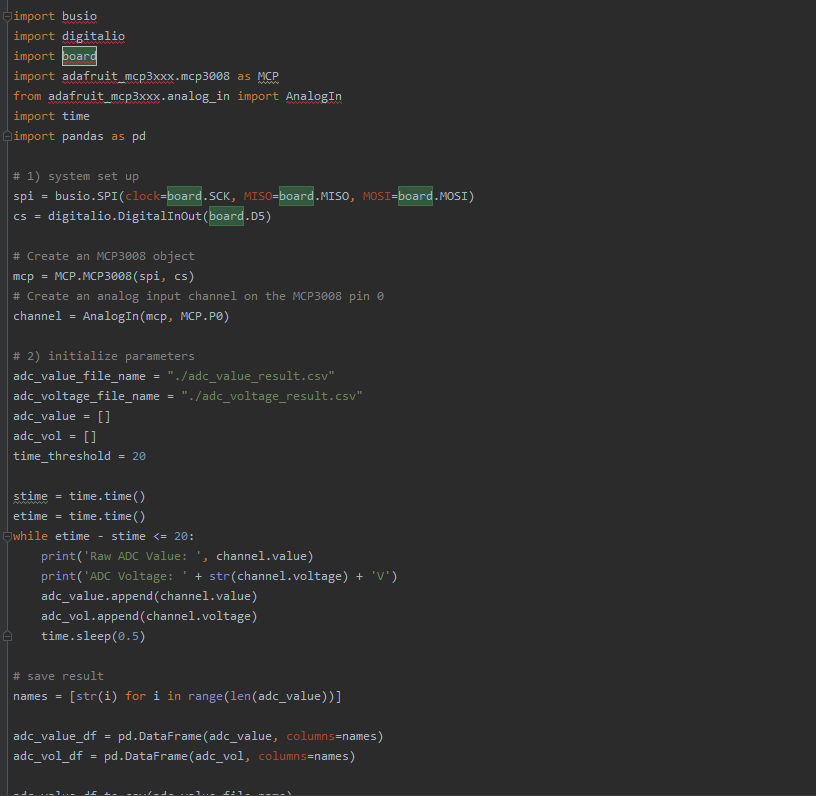
Figure 2. code progress
Problems Encountered
1.When we are going to implement the whole system using the code we wrote, we found there are some bugs in our code. And now we can’t find where the bugs are.

Figure 3. code problem
2.Since we intended to do a lot of work off campus and remotely, we tried to connect the raspberry pi to share internet with our pcs and at-home wifi (no one has a monitor, keyboard, or required HDMI cable off-campus). Also the Cooperation between teammates is limited due to the remote study.
Future Plan
Describe what you plan to do in the next two weeks
- we are going to schedule serval meeting to talk more about the progress each one achived and how to do things better.
- We are going to continue to debug our code to make the code and system can run successfully.
- We are going to design a room, where we can test our detect system and code in serval situations.
Methodology
Phenomena of Interest
We want to measure the light intensity and corresponding temperature at the same time to see the pattern of light intensity and temperature.
Visible Light
Visible light is also part of the electromagnetic spectrum, at higher frequencies that IR radiation discussed previously. The wavelengths for visible light range between 400 -700 nm, and the most common measurement for visible light is its wavelength, in nanometers. All waves in the electromagnetic spectrum travel as the speed of light, commonly known as coefficient c.
Light has natural and artificial sources, including the Sun, fluorescent lamps, incandescent bulbs, LEDs and so on. Most light sources use the at least some part of the full spectrum of visible light but may be skewed towards particular wavelengths of light. Natural light does contain the full spectrum.[1]

Figure 4. visible light spectrum[2]
Temperature
Temperature is a physical quantity that expresses hot and cold. It is the manifestation of thermal energy, present in all matter, which is the source of the occurrence of heat, a flow of energy, when a body is in contact with another that is colder.
Temperature is measured with a thermometer. Thermometers are calibrated in various temperature scales that historically have used various reference points and thermometric substances for definition. The most common scales are the Celsius scale (formerly called centigrade, denoted °C), the Fahrenheit scale (denoted °F), and the Kelvin scale (denoted K), the last of which is predominantly used for scientific purposes by conventions of the International System of Units (SI).
The lowest theoretical temperature is absolute zero, at which no more thermal energy can be extracted from a body. Experimentally, it can only be approached very closely, but not reached, which is recognized in the third law of thermodynamics.[3]
Infrared Radiation
Infrared or IR is a kind of radiation emitted by almost all objects, and is emitted as heat energy. It’s part of the electromagnetic (EM) spectrum, which also includes gamma-rays, x-rays, UV radiation and visible light. EM radiation is created by electric and magnetic oscillation fields perpendicular to each other as well as charged particles traveling in space.[4]
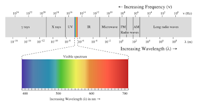
Figure 5. light spectrum[5]
Sensor(s) Used
Describe the sensor(s) you used, e.g. physical principles, static and dynamic behavior, and signal characteristics
MCP3008
This is an Analog to Digital Converter
-
10-bit resolution
-
8 (MCP3008) input channels
-
Single supply operation: 2.7V - 5.5V
-
Industrial temp range: -40°C to +85°C

Figure 6. MCP3008
Photosensitive Light Sensor Module
-
Measure the light level at the bottom
-
Input Voltage: 3.3V to 5V
-
Signal output indicator light
-
LDR module 4 PIN
-
Able to detect ambient brightness and light intensity Adjustable sensitivity

Figure 7. Photosensitive Light Sensor Module
DHT11 Temperature and Humidity Sensor Module
-
Accuracy:±5%
-
Humidity Range:20 ~ 80% RH
-
Mounting Type:Through Hole
-
Operating Temperature:0°C ~ 50°C
-
Output:16b
-
Output Type:Digital
-
Package / Case:Housed Sensor
-
Response Time:1s
-
Sensor Type:Humidity, Temperature
-
Voltage - Supply:3V ~ 5V

Figure 8. Photosensitive Light Sensor Module
HC-SR501 Infrared PIR Motion Sensor Module
-
Voltage: 5V – 20V
-
Power Consumption: 65mA
-
TTL output: 3.3V, 0V
-
Trigger methods: L – disable repeat trigger, H enable repeat trigger
-
Sensing range: less than 120 degree, within 7 meters
-
Temperature: – 15 ~ +70
-
Dimension: 32*24 mm, distance between screw 28mm, M2, Lens dimension in diameter: 23mm
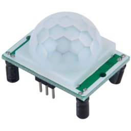
Figure 9. Photosensitive Light Sensor Module
Physical Principle
MCP3008
MCP3008 is an eight channel, 10-bit ADC SAR ADC, which is a successive approximation analog-to-digital converter. The “eight channels” refers to the fact that the MCP3008 is able to receive and process voltages on eight different inputs, number 0-7. These channels can be read in two different ways. The typical fashion is called “single ended input”, where the voltage level is read between the selected voltage reference, VREF, easily selected on the I2C and SPI Education Shield using the VREF jumper, and a ground level shared in common with the circuit doing the measuring and the circuit being measured. The 10 bits refers to the sampling range of the ADC itself. B0000000000 = 0 and B1111111111 = 1023, meaning you can measure 1024 different voltage levels, typically between ground and VREF. So if you have a 5V reference, and can split it 1024 times, each step would be equivalent to a measurement of 0.0049V. With the 3V3 reference, each step is equivalent to a measurement of 0.0032V. [6]

Figure 10. MCP3008[7]
Photosensitive Light Sensor Module
The photoresistor is based on the internal photoelectric effect. Photosensitive resistors are formed by mounting electrode leads at both ends of the semiconductor photosensitive material and encapsulating them in a tube case with a transparent window. In order to increase the sensitivity, the two electrodes are often made into a comb shape. The materials used to make photoresistors are mainly semiconductors such as metal sulfides, selenides, and tellurides. Coating, spraying, sintering and other methods are used to make a very thin photoresistor and a comb-shaped ohmic electrode on an insulating substrate. The leads are connected and sealed in a sealed housing with a light-transmitting mirror to prevent its sensitivity from being affected by moisture. After the incident light disappears, the electron-hole pairs generated by the photon excitation will recombine, and the resistance of the photoresistor will return to its original value. When a voltage is applied to the metal electrodes at both ends of the photoresistor, a current passes through it. When the photoresistor is irradiated by the light with a certain wavelength, the current will increase with the light intensity, thereby achieving photoelectric conversion. The photoresistor has no polarity and is purely a resistive device. It can be used with both DC voltage and AC voltage. The conductivity of a semiconductor depends on the number of carriers in the semiconductor’s conduction band.[8]

Figure 11. Photosensitive Light Sensor Module[9]
DHT11 Temperature and Humidity Sensor Module
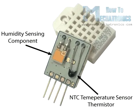
Figure 12. DHT11 Temperature and Humidity Sensor Module[10]
For measuring humidity they use the humidity sensing component which has two electrodes with moisture holding substrate between them. Between the electrodes, there is a moisture-holding substrate that can absorb water vapor. The substrate releases free ions, which increases the conductivity between the electrode, as water vapor enters it. Thus, the humidity sensing component is a moisture holding substrate with electrodes applied to the surface. When water vapor is absorbed by the substrate, ions are released by the substrate which increases the conductivity between the electrodes. The change in resistance between the two electrodes is proportional to the relative humidity. Higher relative humidity decreases the resistance between the electrodes, while lower relative humidity increases the resistance between the electrodes[11]
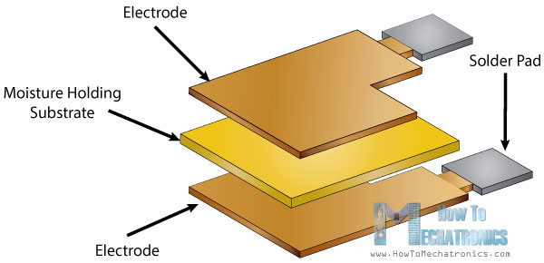
Figure 13. Humidity sensor work principles[12]
A thermistor is actually a variable resistor that changes its resistance with change of the temperature. These sensors are made by sintering of semiconductive materials such as ceramics or polymers in order to provide larger changes in the resistance with just small changes in temperature. The term “NTC” means “Negative Temperature Coefficient”, which means that the resistance decreases with increase of the temperature.[13]
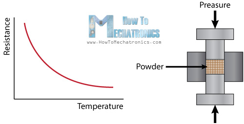
Figure 14. Temperature sensor work principles[13]
Negative temperature coefficient of resistance thermistors, or NTC thermistors for short, reduce or decrease their resistive value as the operating temperature around them increases. Generally, NTC thermistors are the most commonly used type of temperature sensors as they can be used in virtually any type of equipment where temperature plays a role. NTC temperature thermistors have a negative electrical resistance versus temperature (R/T) relationship. The relatively large negative response of an NTC thermistor means that even small changes in temperature can cause significant changes in their electrical resistance. This makes them ideal for accurate temperature measurement and control.[14]
Another important characteristic of a thermistor is its “B” value. B value will define the thermistors resistive value at a first temperature or base point, called T1, and the thermistors resistive value at a second temperature point.[15]
HC-SR501 Infrared PIR Motion Sensor Module
PIR sensor is specially designed to detect such levels of infrared radiation. It basically consists of two main parts: A Pyroelectric Sensor and A special lens called Fresnel lens which focuses the infrared signals onto the pyroelectric sensor.

Figure 15. Temperature sensor work principles[16]
There are two potentiometers on the back of the PIR chip to control the sensitivity of the PIR and the delay time. The sensitivity of the PIR sensor is the sensing capability; the sensor can detect anywhere from between 3 to 7 meters, adjusted by the potentiometer. Delay time is the amount of time that the PIR sensor will remain high after being triggered by motion. It can help reduce redundant readings when counting fast-moving objects and provides flexibility in sensor setup. The delay time can be set to read high for 3 seconds to 5 minutes, and is always followed by 3 seconds of low output where no readings can be made. Another feature of the PIR sensor is the Trigger Mode, which has a Repeatable (H mode) and Single (L mode) option. The single trigger option means that the time delay begins when the motion is first detected, and ignores any additional triggers while remaining high for the rest of the delay time. Repeatable triggers mean that ever motion detection will reset the sensor’s delay time to restart count[17].
Signal Conditioning and Processing
Decision making
The decision making for the automatic adjustment of light intensity is based on the scenarios that the system detects. Here we have 3 states of interests: No led opening, One LED opening, and Two LED opening. To make a smarter decision, we make the following decision making workflow:
#
for every sampling:

    human = pir.result
    current_light_intensity = light_sensor.result

    if there exists human in the room:

        if current light is too bright:
            if there is still openning LED
                close one LED
        else if current light is too dark:
            if the # of LED is less than 2:
                open one LED
    else:

        close all LED
The workflow above is simple and intuitive. However, through several tests, we found that the human detection part is not stable. That is, even if there is continuously something warm in front of the PIR sensor, it still produces some “FALSE” feedback. The reasons why this happens may be: 1) the measure range of PIR is not enough; 2) the connection between PIR and the control system is not stable
We then found that even if one single signal is not stable, a series of signals will produce a significant portion of right feedback. Based on this finding, we develop a context-based signal prediction algorithm:
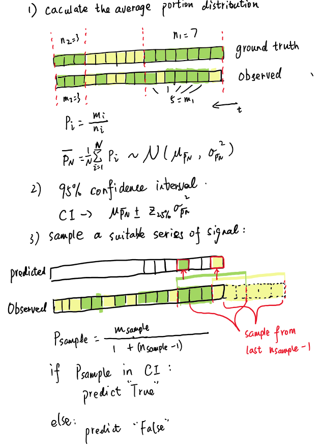
Figure 16. context algorithm
Experiments and Results
Implementation of the context-based human detection algorithm
The distribution of the portion samples

Figure 17. Portion distribution
Result of the confidence interval is
- (0.566, 0.847)
Note that we only use the minimum of interval as the threshold.
The toy model
We set up a toy model to simulate the real environment (Figure 18). The hardware system is on the top of the model. And there is a tiny tiger sitting inside the model as our tested objectives

Figure 18. Experiment environment
Discussion
In this project, we present a real-life issue, how to control our indoor light and temperature more intelligent. We solve this problem by selecting the sensors, validation method, and testing process we learned from class, to achieve our goals. Those goals are to successfully achieve a way to control our light system automatically when the light doesn’t accommodate to our preference. After knowing what phenomena we interest, we choose DHT 11, PIR and Photosensitive Light Sensor to achieve our goals. Then we design the experiment environment, circuit, and also the code to achieve those goals.
With collecting data from sensors, calibration and sending commands to the actuator, we become familiar with the complete process of using sensors.
Although, we have spent a lot of time in this project. Due to the limitation of the equipment and cooperation, There are some imperfections, for example, we just use DHT 11 to detect the temperature and with the result, we did nothing. So, if we have a chance, we can design a more mature system, using some other equimpent to adjust the temperature. We just use one light sensor to detect light intensity, which causes we can’t tell the environmental light intensity and artificial light intensity. So there are some problems, we want to solve in the future.
With this group project, we also different kinds of problems, by solving them enhance our knowledge about sensor and code.
Thanks to the assistance of Professor Mario and TAs, their help and patience make us finish this project successfully.
Referrence
[1] The Electromagnetic Spectrum. Mini Physics, https://www.miniphysics.com/electromagnetic-spectrum_25.html
[2] The Sky Is Only Sometimes Blue, https://whybecausescience.wordpress.com/tag/electromagnetic-spectrum/
[3] Temperature and Thermometers, https://www.physicsclassroom.com/class/thermalP/Lesson-1/Temperature-and-Thermometers
[4] The Electromagnetic Spectrum, https://courses.lumenlearning.com/physics/chapter/24-3-the-electromagnetic-spectrum/
[5] What is Infrared Radiation (IR)?, http://how-it-looks.blogspot.com/2010/01/what-is-infrared-radiation-ir.html
[6] MCP3008 Tutorial 01: Functionality Overview, https://rheingoldheavy.com/mcp3008-tutorial-01-functionality-overview/
[7] MCP3008 8-Channel 10-Bit ADC With SPI, https://osoyoo.com/2017/07/18/mcp3008-8-channel-10-bit-adc-with-spi/
[8],[9] Photoresistor Basics: Types, Principles and Applications, https://www.utmel.com/blog/categories/resistor/photoresistor-basics-types-principles-and-applications
[10],[11],[12],[13] DHT11 & DHT22 Sensors Temperature and Humidity Tutorial using Arduino, https://howtomechatronics.com/tutorials/arduino/dht11-dht22-sensors-temperature-and-humidity-tutorial-using-arduino/#:~:text=DHT11%20%2F%20DHT22%20Working%20Principle&text=They%20consist%20of%20a%20humidity,back%20side%20of%20the%20sensor.&text=So%20as%20the%20humidity%20changes,resistance%20between%20these%20electrodes%20changes.
[14],[15] Electronics Tutorials, https://www.electronics-tutorials.ws/io/thermistors.html
[16],[17] How HC-SR501 PIR Sensor Works & Interface It With Arduino, https://lastminuteengineers.com/pir-sensor-arduino-tutorial/